1222 PERFORMANCE OSCILLATOR
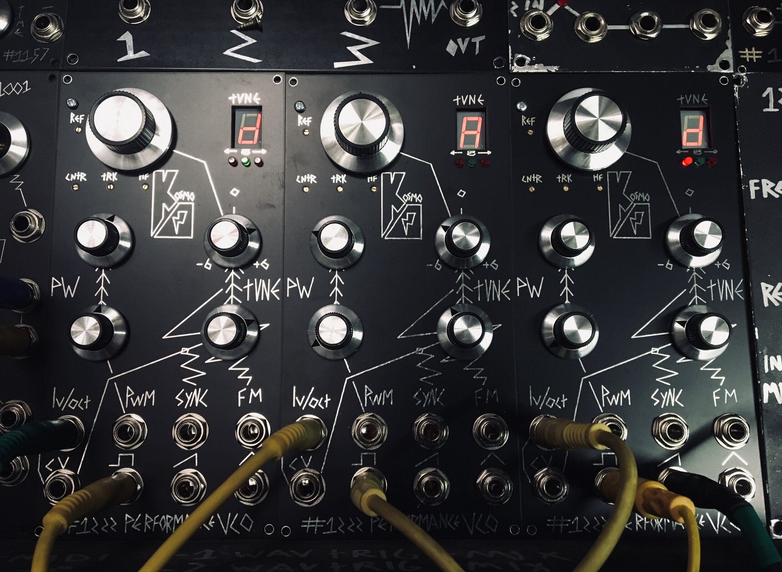
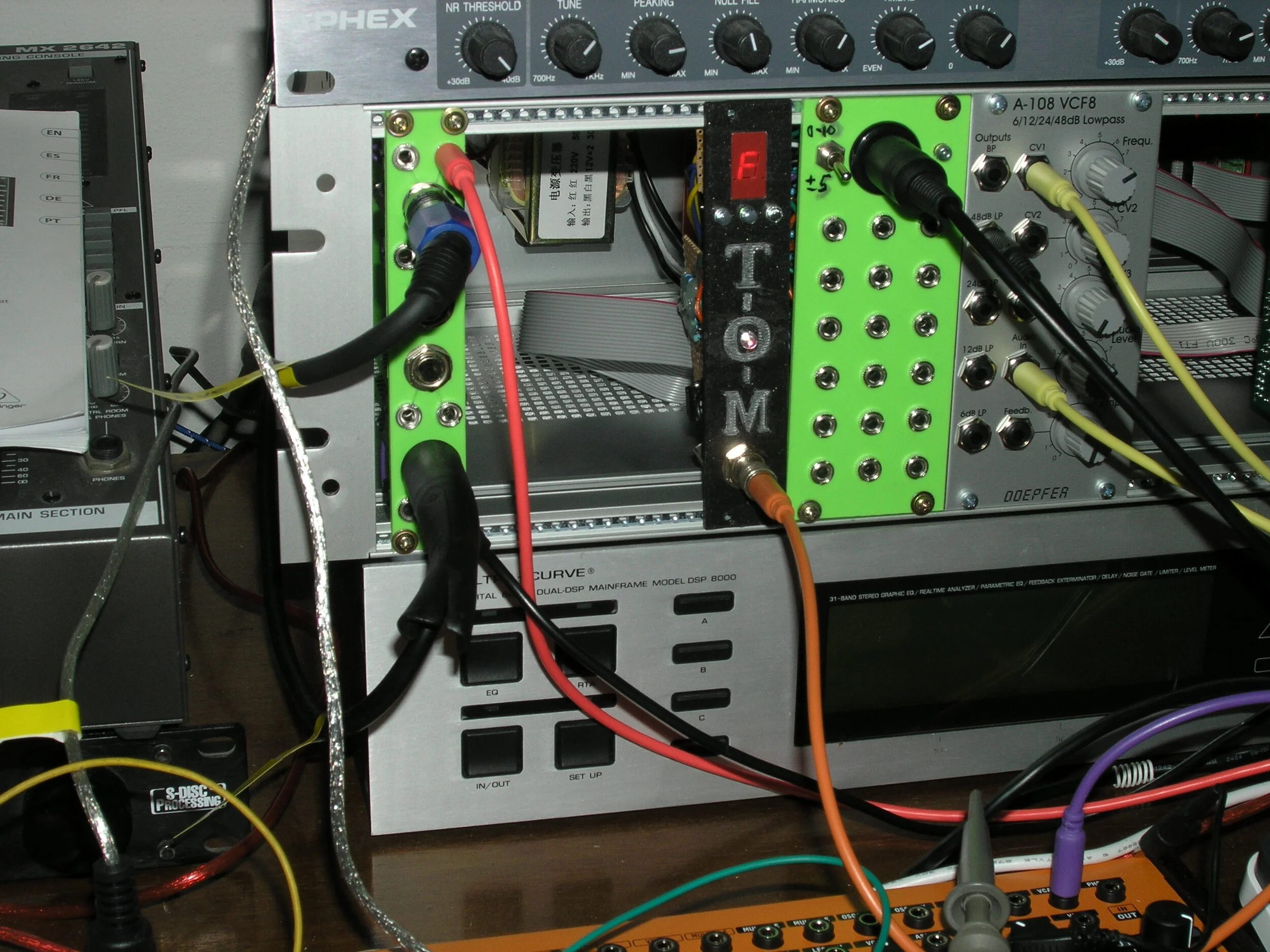
a tad dirty from tour but these were my prototypes!
**NOTE* in the first batch of pcb’s it has come to my attention i have mispacked a handful, so there are a few rogue VCO’s in the wild with lfo pcb’s instead of vco pcb’s so get in contact on the contact form if your the lucky person with a free lfo pcb, and ill send out the right one! :)
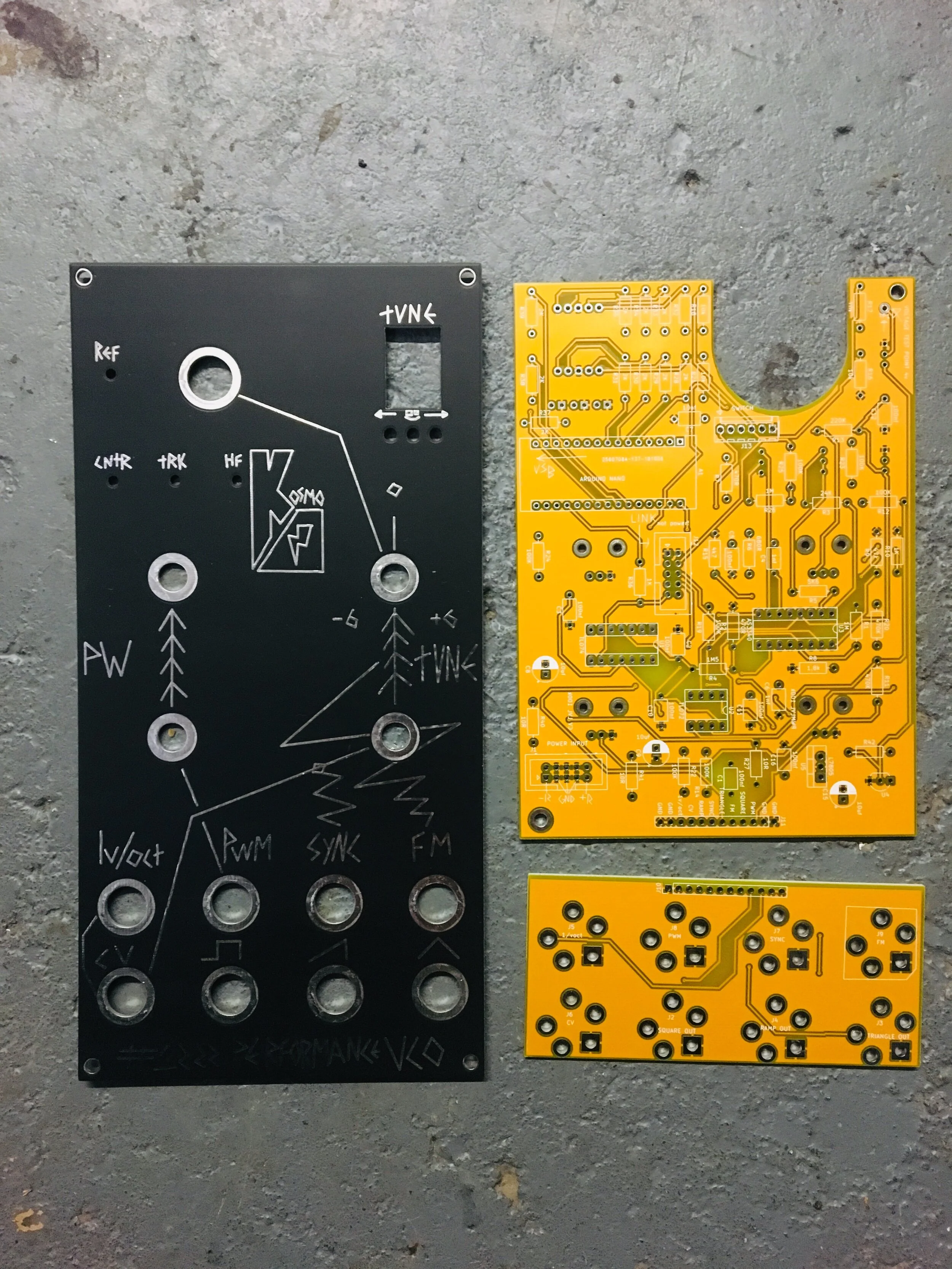
PCB/PANELS ARE NOW AVAILABLE ON THE STORE
The 1222 Performance VCO is my first Oscillator PCB Design.
Born from frustration of playing shows, or not having a tuner to hand and getting in tune enough to get going, instead of sitting around being out of tune. I tested it on my November tour, and did some fine tweaks to it afterwards.
Its also got an octave knob. a fine tune knob that is exactly an octave with a centre point of C making it easy to find the note you need. it is a rather standard oscillator apart from that, and in my opinion thats what you need.
Big simple controls, pulse width, PWM, fine tune, Extra CV, Sync, FM, Square, Ramp and Triangle outputs.
It also has a rear connection called LINK, which will be for future use, as i will be making an oscillator drive a nice means of driving lots of oscillators at once, as well as a mixer module so no need to patch all of the oscillators together they will be connected from the back. A final design is like a cross mod module that will turn em into a sort of fart box thing. This is all future ideas, but if you cant wait check the schematic it will make sense!
The build is reasonably simple it is explained in videos below. you will need to be able to connect an arduino nano to a computer, the code is available below.
Temperature drift. unknowingly i took these on tour to the extremes of temperatures. they spent most of their time in a 0 degrees celsius van, giving it plenty of time to cool the whole case through. then they were carried into room temperature rooms and immediately sound-checked. Then they slowly heat up throughout the night, and as more people enter the room the hotter the room gets and the hotter the case and oscillators get. Then the time comes to play the show! and boom, it’s a tiny bit out. The change in tune wasn’t massive, only a few cents but i was very thankful for the tuners.. I noticed this effect more at smaller gigs than larger gig. i guess smaller rooms heat up more like a big old oven. However when playing the gigs it seems like there had finally been a stable temperature reached and i didn’t really need to set the tuning in the gig itself. it was notably the time between sound check and show time.
Anyway below is everything you need. any questions fire over, at the bottom is an FAQ with past problems/questions.
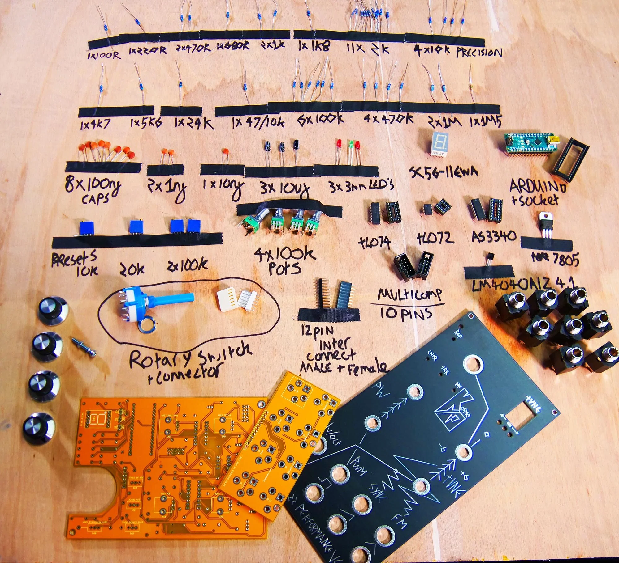
The Bill of materials links are the first i got to, if you look around you may find cheaper, these are UK also. if anyone in the US makes a mouser cart, please send my way it would be useful! i will try to make one, however there is no telling when that will happen.
below is the first video on this module, this was before tour, these prototypes i took on tour and they are largely the same as the finished things. The tuner code is a tad more finessed, plus i didn’t spend ages calibrating these!.
I will be adding more videos on this in the coming week.
So below is the information on building this, including the schematic, bill of materials and code, i have also attached the kicad file of the schematic if you want to mess around with it. right at the bottom of the page i will be adding things to think about and look out for hopefully answer some questions before they have been asked!
if your struggling to find components check out this forum thread CHEAP COMPONENT SEARCH
Jos Bouten has made an alternative to the above which is basically a cleaned up version of the above code, with all of the frequencies for the notes all placed into a nice neat table! check it out here JOS's GITHUB PAGE. works on all arduino nanos, doesn’t work on arduino every.
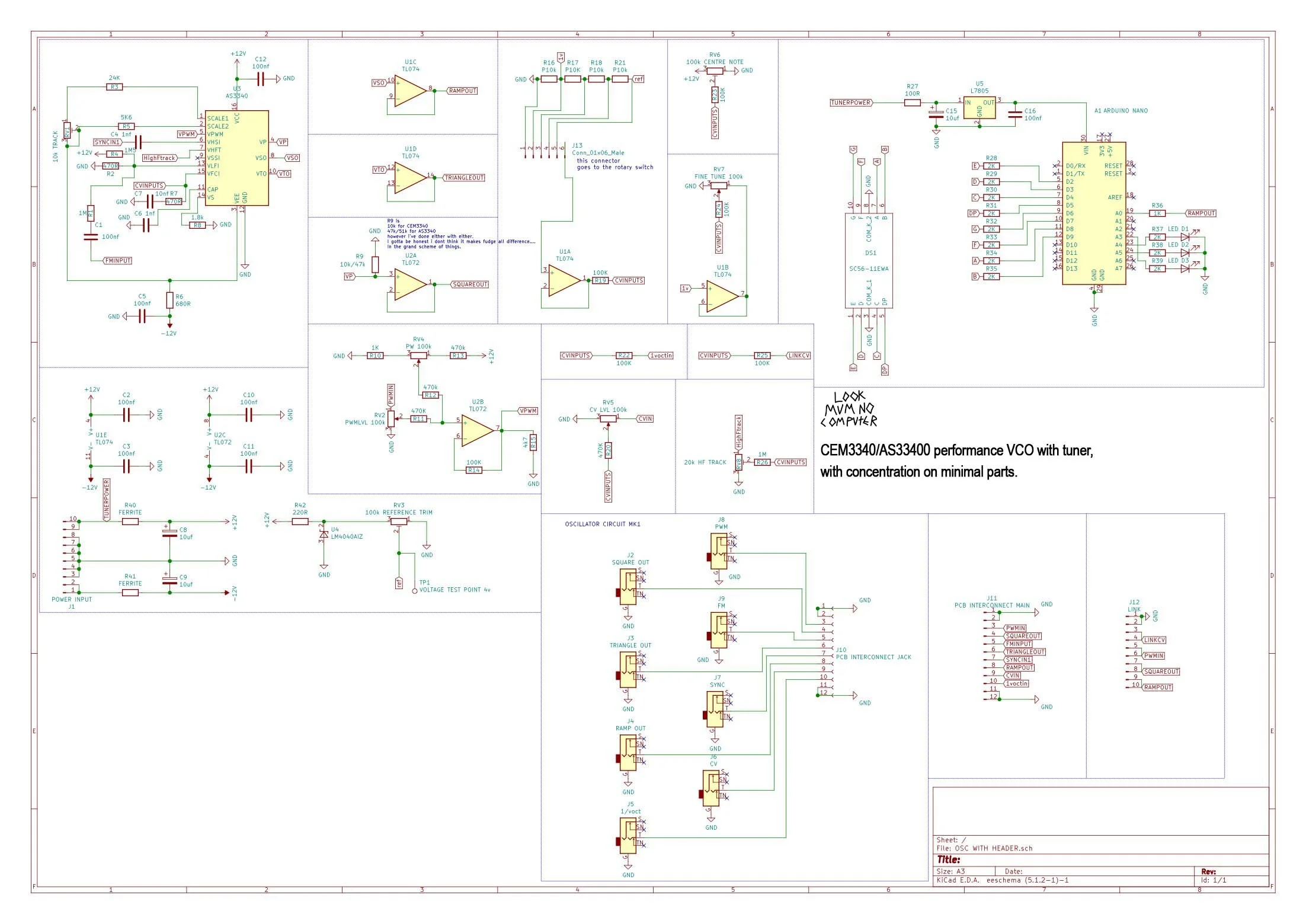
Cem3340 schematic
this is the tuner aspect of the schematic, to keep it simple what i have done is make it slightly dimmer (i had it quite bright initially but it kind of takes too much of your vision up so this is a blessing in disguise. I will be adding a strip board version of the above.
A few people have asked why have i opted on a whole Arduino to do this job? well the answer is cost and simplicity. If i was to design this with just an Atmega chip, i am expecting the builder to climb another potentially heavy learning curve. As not everybody knows how to program one, it’s just another step to complicate things. As for price, because you can get cheap Arduino’s for under £3 nowadays, and an Atmega chip with the Arduino boot loader is still £1 or so, the pro’s outweighed the cons.
Why have you not used an LED driver? the reason is for simplicity.
But wont that add unnecessary strain onto the Arduino? The Atmega 328p chip is rated to output a maximum of 40ma. with the above design you have a max of 9 LED’s on at once, and the current limiting resistors are massive, to make them slightly dimmer so they are not off putting, with these massive 2k resistors each LED saps at a generous calculation about 2ma, so that adds up to about 18ma round it off to 20ma, thats half of what the Atmega chip can take. So! i think this cut corner is justified.
Why not use multiplexers to reduce the amount of pins used? This was the initial plan to do this and use an ATtiny chip, however a few issues arose, the first i touched on about simplicity, making it simpler with just 1 chip actually makes it more complicated, increasing programming steps etc! However, the main issue i had was usually with screens you are multiplexing the lights on the seven segment display so they are never actually all on at once, in initial experiments i found this to actually add a tiny bit of noise to the oscillator output as the circuit was in such close proximity. Im sure i could have figured out some preventative measures, but as the first reason was also dawning on me. i opted for a simpler design.
This is the actual VCO aspect of the schematic, its largely based on the datasheet. all outputs are buffered, note i am using the bare minimum amount of components here, to ease with the build process. Remember if it sounds right it is right!
You’ll notice as per the Datasheet the AS3340 and the CEM3340 require different pull down resistors for the square output. ILL LET YOU INTO A LITTLE SECRET. it doesn’t make a difference. infact in all the ones i have build i just split the difference and put a 20k in place of the 47/10k, and for all intended purposes its fine, its your life don’t be scared by naysayers and pedantic’s on the internet.
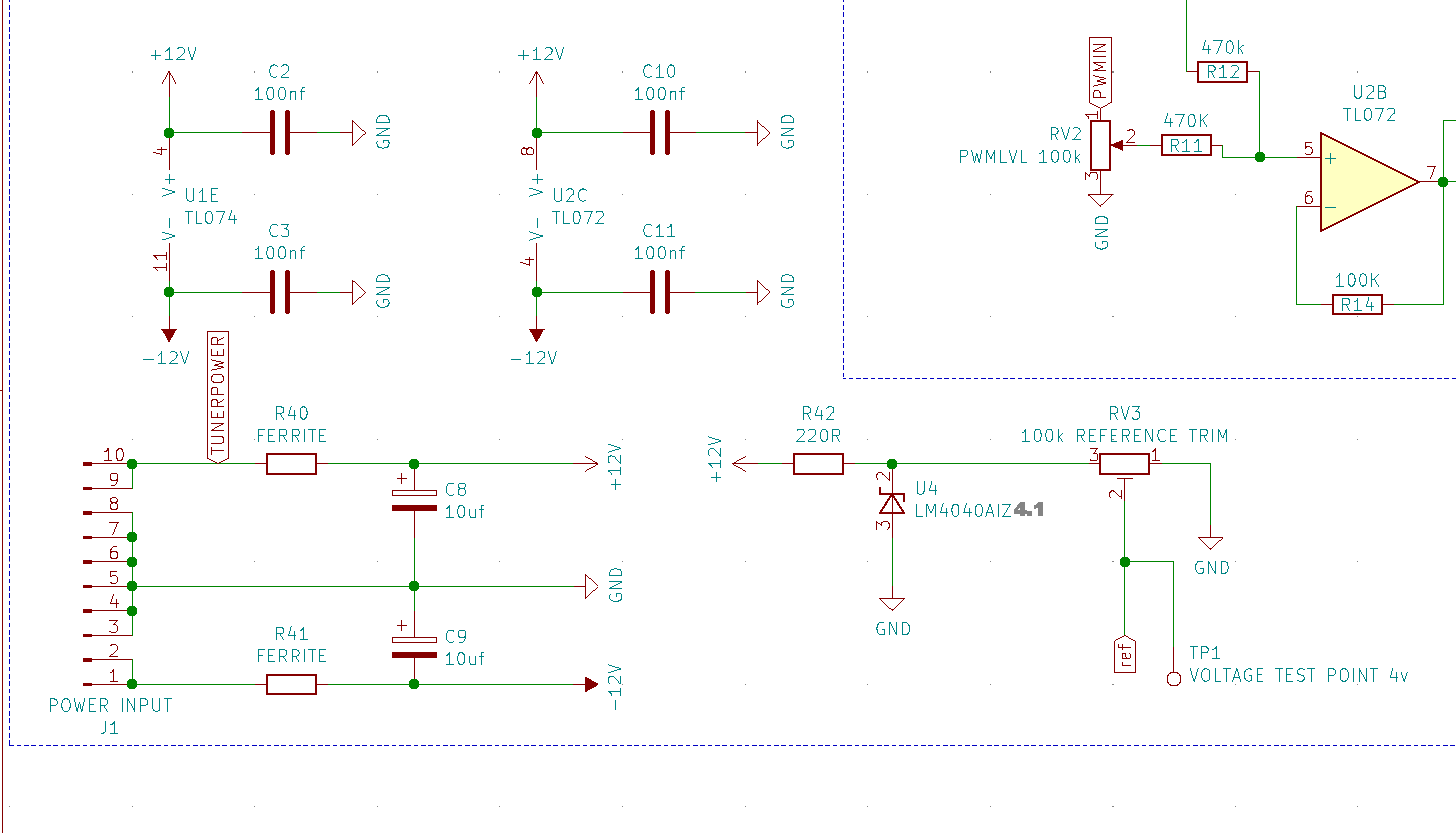
This is the power part, you’ll see it looks very similar to most eurorack power situations, thats because it is. you’ll notice in my other projects i don’t ferrites but i use 10r resistors, however the 10r resistors in this design actually accentuate the cem3340’s PWM tuning drift. so its a no no in this design, so i added the ferrite beads for some dignity at least (BUT ILL LET YOU INTO ANOTHER SECRET) in all the ones i have built i didn’t bother putting them in and instead just wired in just a leg of a resistor. because yet again, don’t let the pedantic’s get you downnnnn.
the voltage reference is from a shunt regulator, watch out and make sure to get the LM4040AIZ 4.1 other letters mean its a crapper version and more susceptible to temperature drift. this solution was suggested by a kind commenter on a youtube vid and i’m very sorry i cant find that comment but thank you and after research i have gone for this specific one.
Also! if your lazy a heads up you can if you really couldnt be bother, skip those 4 100n capacitors and those 10uf resistors, they are decoupling capacitors and electrolytic capacitors, i include them because they are a sort of standard, however in audio settings like this, to be honest the difference is rather minimal. yet again!!!! don’t let the pedantic’s get you downnnnn its music, not astro physics.
Finally this section is the jack section, thats all it is. jacks jacks and more jacks, oh and the link connection this is where you can see what is available on that link connector, in future this is for an oscillator driver which will add portamento and other functions to a synth voice whilst removing a couple of cables. Also planned is a mixer for the same reason and a cross modulating module to kinda make it all like a big stinky fart box.
A note about the tuner
So the tuners intended purpose is to get you in the ball park of acceptable tuning, trust me it happens, you’re in the zone and knock a tuning knob on 1 oscillator out of god knows how many oscillators playing at the same time, you’re potentially in trouble town. This is on an analog oscillator which by its very being is an inaccurate beast (the reason we love em) so technically the marriage is unconventional. the tuner has been adjusted to be a tad more tolerant of this, like a guitar usually within 10-15 percent of a note your golden. The one risk i thought of about adding a tuner to an oscillator is you begin to listen with your eyes, bringing out the pedantic within which is never a good thing! hence why i made it slightly dimmer, so it isn’t screaming at you LOOK IM A TINY BIT OUT OF TUNE, SO DON’T LISTEN TO YOUR EARS LOOOOK AT MEEEEEE. thats not its purpose, its a fail safe, and a nice screen :)
like i say in the calibration vid! it doesn’t need to be a tuner maybe make it into a rotating circle that speeds up with the oscillator i dunno. but if you do mess around with it or improve it don’t be shy to let me know and i’ll include it on this page, obviously with a shout out to you!
a note about the daughter board pointed out by antoine.pasde2 on the forum. “JACKS TO BE SOLDERED ON THIS SIDE” means put the jacks on this side. Im aware this could be mis interpreted as put the solder on this side. but it does not.
CEM3340 or AS3340?
So the original CEM3340 is the bee’s knees, however there is a cheaper clone called the AS3340 and i gotta say, i can’t tell the damn difference! links to bother :-
CEM3340
AS3340
Good info on implementation of the CEM3340 can be found here :-
also this video of mine covers a stripboard layout which i will be adding to in the coming days :-
FORUM
I have just started a forum which hopefully will soon be filled of all stuff regarding building these modules! from mouser carts to build questions, you name it you can get to it click here.
Any questions, or you feel i have missed something out, please contact me and ill answer or get it added. thanks.
US folk or anyone not based in uk for that matter i know its not super useful i am including uk sources for the parts in the Bill of Materials. however thats where i get them. If you manage to find sources that work for you in your country please contact me and ill put them on this site so it can help others! as it stands check below :-
Todd says :- I've ordered the 9mm potentiometers from Thonk in the past, but I found this may be a better source for US folks. https://modularaddict.com/parts/potentiometers-1/9mm-potentiometers. Oh and this is a good place for knobs https://lovemyswitches.com/knobs/?_bc_fsnf=1&Shaft+Type=1%2F4%22+Smooth+Shaft
Antoine says :- I just ordered these pots and jack sockets from AliExpress, they look like the right ones. https://www.aliexpress.com/item/32965143843.html
FAQ :
the 10k/47k resistor is down to the only difference in the datasheets of the as3340 and the cem3340. the cem3340 asks for a 10k resistor here, and the as3340 asks for a 47k, in the video i say i used a 20k just in the middle as i have not noticed and difference however its up to you which value you go for.
the LM4040AIZ make sure you get the 4.1! as someone got the 2.0 version and we found out after a bit of emailing back and forth about this. the 4.1 means it regulates to 4.1v. and the trim pot brings that down to 4.0v
above is a stripboard version of the tuner, below is download for the slightly adjust code to make the layout a bit simpler.
an image of Jos’s “Tune-O-Matic” you will have seen above jos actually made a cleaner version of the tuner code also! JOS's GITHUB PAGE Also he has posted info on his build on the LOOK MUM NO COMPUTER forum here

