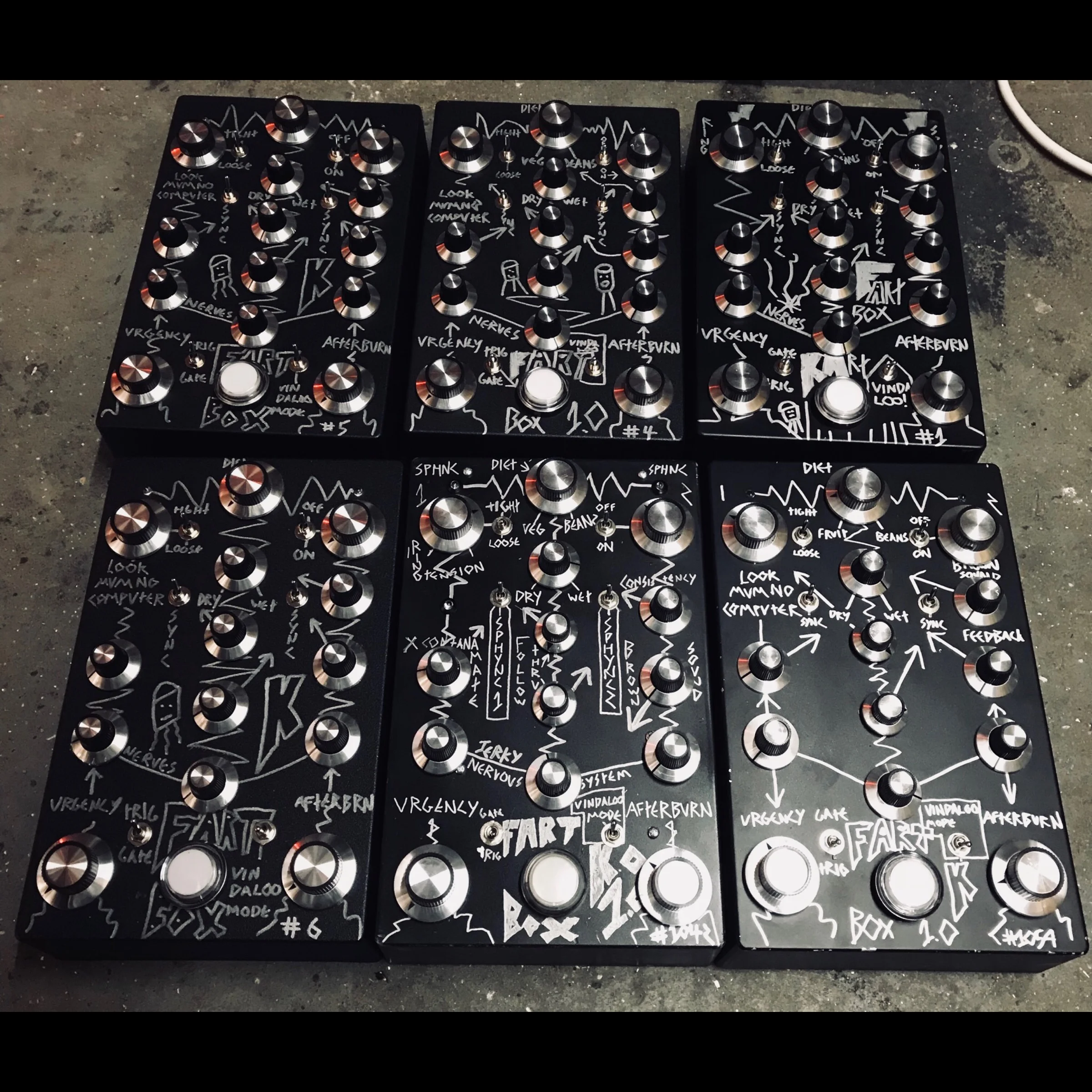
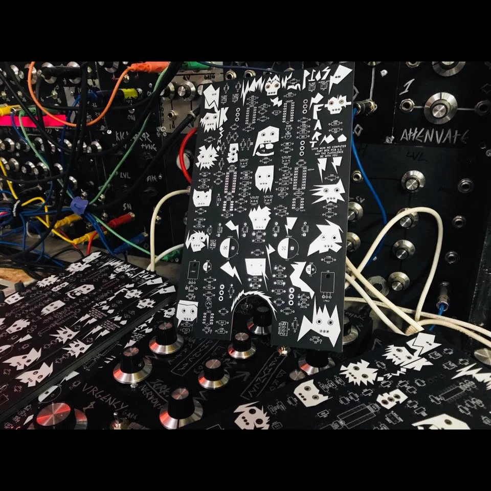
About
i made a small amount of pcb’s for this project for my november 2019 tour, sadly i wont be doing any more but there is nothing stopping you from having a bash at the kicad file below!
FOR PEOPLE WHO HAVE BOUGHT THE PCB ON TOUR :-
the above bill of materials is from todd entriken, however the parta are rather self explanatory from the labelling on the pcb. also check the FORUM on peoples builds over here.
things to note. the top potentiometer is 5k. and the bottom two are 1M and the rest are 100K. LINEAR
remember there isn’t much documentation for this! so proceed with caution!!!
DRILL GUIDE AND EXTRA REFERENCES AVAILABLE HERE
THE ENCLOSURE I USE, But you can use any! is the HAMMOND 1550 https://www.rapidonline.com/hammond-1550jbk-ip54-diecast-aluminium-enclosure-black-275-x-175-x-67mm-30-4376
as for the 12v AC AC power any will work! it needs to be AC AC not AC DC though something like this :-
REGARDING THE BUTTON CONNECTIONS:-
as your looking at the pcb from the front, from the top to bottom the pins on that connector go :- 1 Trigger in,2 12v, 3 LED, 4 GND. so you solder the 12v and the trigger in to either side of the push switch, then LED and GND to the plus and minus of the signal LED.
FAQ
Can i power the fart box with my eurorack power supply?
YES
You can just skip a few components on the fart box as it has a built in power filter
No need to solder in :-
D9
D10
D11
D12
D13
D14
U8
U9
C17
C18
The above are the components you won’t need if your powering it from the Eurorack. You can still put them in, it will work either way
Solder the eurorack +12v to the positive leg of C4
Solder the eurorack -12v to the negative leg of C5
Solder GND to the negative leg of C4
That will make it powered by the eurorack power


