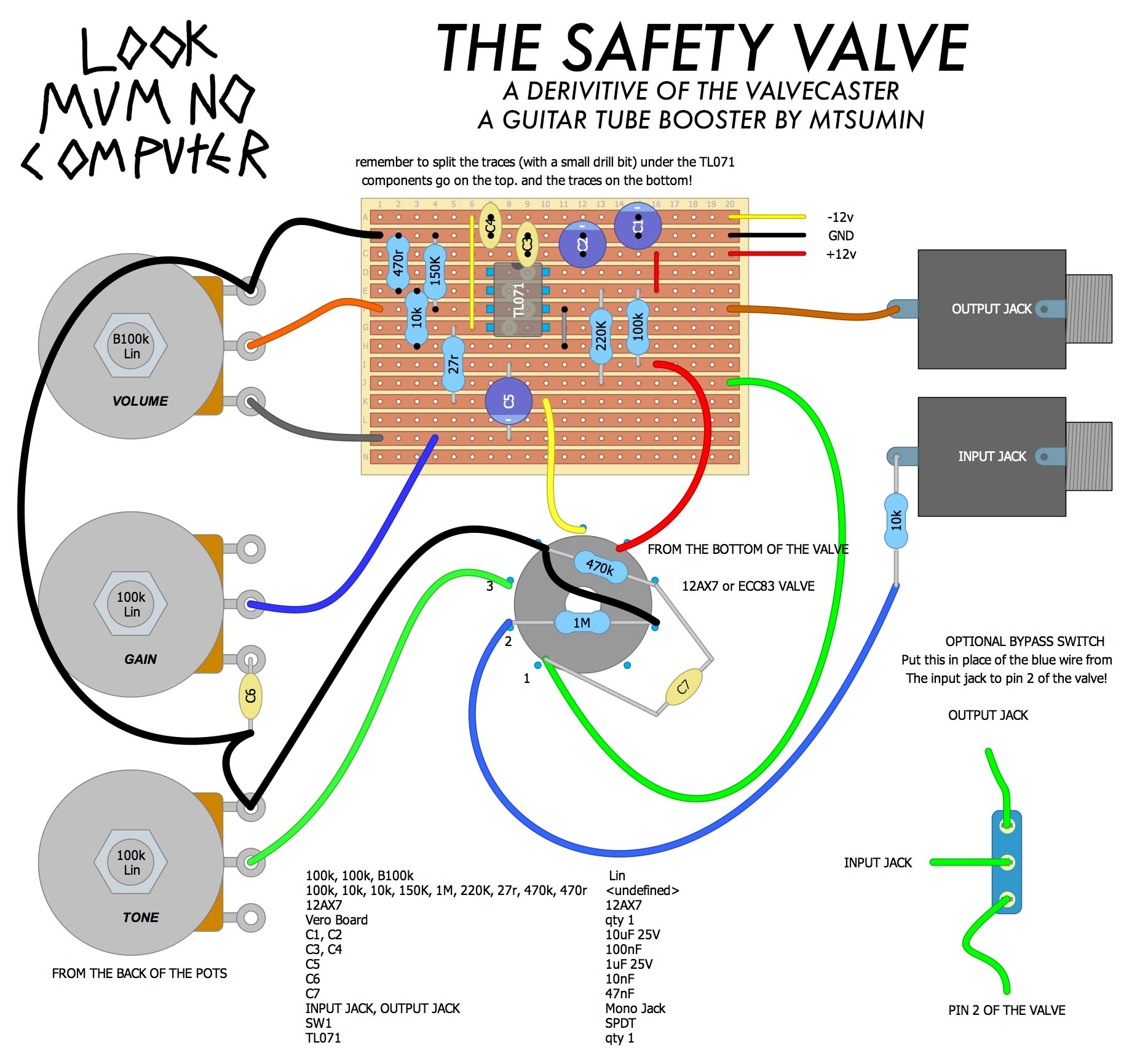
THE SAFETY VALVE
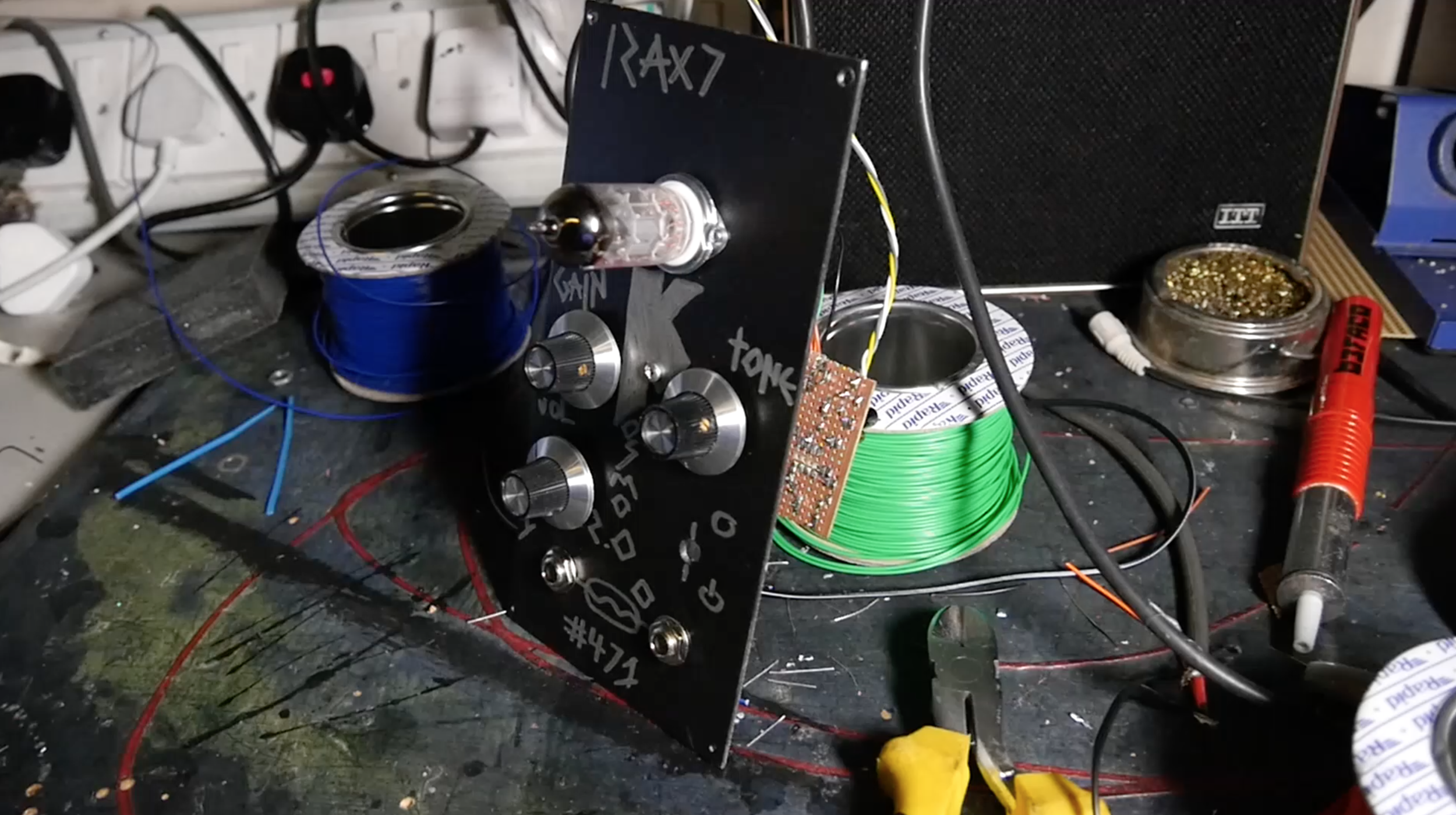
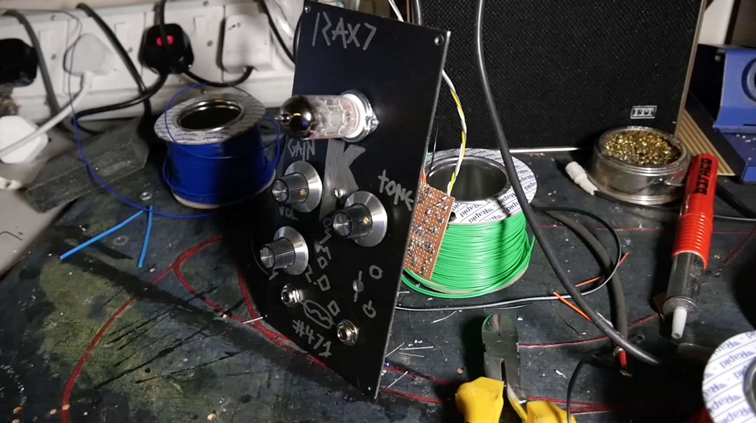
So i Designed this module because i felt there was a lack of low voltage projects involving big ole tubes.
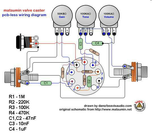
In the DIY guitar pedal Community there's a design floating around called the VALVECASTER, by Matsumin. Which i have built a number of times throughout the years. Its very simple. With only a number of components, The project can be completely soldered to the back of the valve socket! as seen below in this image from the now in active BEAVIS AUDIO RESEARCH (which was an amazing resource on the web :( )
Above is the PCB-less layout for the valvecaster from the now defunct beavis audio research. As you can see the project is very simple!
PS IF YOU ARE BEAVIS PLEASE FIRE US AN EMAIL IF YOU AINT HAPPY WITH ME SHARING THIS, just sadly i cant find a link to the page these were originally placed, :(, its all gone down!
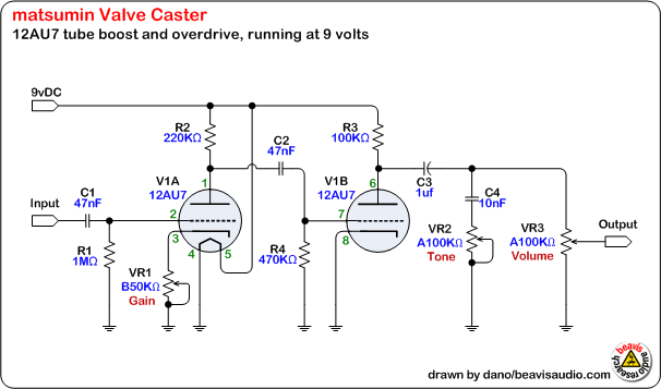
The Valvecaster is using both stages of the Dual Triode Valve called the 12AX7 (also known as the ECC83), A valve commonly used in guitar amps, as a pre amp valve. The schematic looks the same as pretty much all guitar amp pre amp stages. Just the values are slightly adjusted to cope with the STARVED PLATES (starved triode plates in the valve, that usually require a lot more power to ionize or something, im lost at that point) When they are starved they actually become more un predictable, and "frazzlier" you'll notice this if you have ever turned on something valve whilst playing through it, it will start quite quiet and frazzly for a second or two before it becomes the proper sound....
This is the schematic, yet again drawn by beavis audio. As you can see there are 2 big circles! but only one valve? thats because the valve is a dual triode valve, DUAL! so there are 2 of the same components in 1 vacuum capsule. They are the same. You'll notice the first one has 2 extra pins, (pin 4 and 5) these are not part of the valve components, its just the way its drawn, this is actually the heating filament, Between pin 4 and 5 is a coil much like in a lightbulb. in the 12AX7 you put 6 volts through it and it starts to glow and heats the valves up to a working temperature.
So whats the difference between this and the Safety Valve?
The Valvecaster is designed for guitar line levels, Which is super doooper quiet compared to synth levels. You could get away with using something like this Stomp box adapter by Ken Stone CGS. Or a Ready built eurorack module like the S.B.G By ALM, These modules, bring synth line down to go into the effects pedal without clipping, then amplifies it back up again to make it loud enough again.
But thats a bit inconvenient, cus you cant use it on its own, The other sad thing is the 12AX7 is not a power amp valve, so it wont get loud enough on its own anyway!
So why don't we optimise the circuit above to just work with synth line level straight off the bat.
Below is my design seen in the video! its basically the Valvecaster, with a couple of value changes This is more Gainy than the Valvecaster, and brighter, just to work with synths better and sound more fudged up! It also has an op amp added at the end to multiply the signal, and its super loud! i figured the more the merrier.
When i started out i never knew what type of resistors or caps or whatever to get, i have since worked out they make fuck all difference, in a circuit that is down to no accuracy and more taste, you can use anything with the right (or even a bit wrong) values! just mess around, maybe youll find a better sound anyway! For instance the 200k and 100k resistors, if you lower one of them a bit the gain will go up! The 220k will adjust the gain of the first gain stage, and the 100k will adjust the second.
But to make this easy! heres the links to the stuff above on rapid electronics and eBay my two faveourite online shops.
- RESISTORS A RESISTOR PACK, MULTIPLE RESISTORS ALL IN ONE PACK!
- 2 x 10uf Electrolytic Capacitors
- 1 x 1uf Electrolytic Capacitor
- 2 x 100nf Ceramic Capacitors
THINK OF YOUR POWERING???
if your planning of wiring it up to a eurorack synth, maybe look at getting one of these, and use your noggin to line up the +12v GND and -12V to where they should be on this
- this will connect to a eurorack ribbon connector
I use these :-
- This is in the cabinet on a bit of stripboard wired to the power supply
- This is the connector at the end of the 3 wires that are coming from the module
- These are the metal crimps that go inside the connector you crimp to the wires!
you can get a proper crimp tool. but i just use some skinny nosed plyers and a little bit of patience, a crimping tool has always been on my buy list but never bothered haha.
Also whilst im here! heres the power supply i use!
which is plugged into this AC/AC 12v adapter to the wall!
THE STANDOFF AND BOLTS!
- Hex Stand off to mount the pcb!
- M3 bolts to bolt the pcb and panel to the standoff
MODS
Right so this isn't enough?
Ok so heres some mods to think about!
- Add a feedback on switch to send it into oscillation mode. Just solder an on off switch between the input jack and the output jack! that way when you flick that switch on it will start feeding back on itself and act like an oscillator! like i did at the end of my video on it.
- Voltage control? sadly this aint too easy, because the potentiometers are acting as resistors, so either use a vactrol (simplest form in this video) or make a complicated VCA circuit between the pins of the potentiometer like in a lot of other circuits, but meh! too much soldering for one day. you only live once, just go buy a metasonix panel! ha. joking you can do that! thats what i have done on one the other day ill pop a schematic up one day. but to be honest on a overdrive circuit like this there isn't much point.
- Make a voltage control on the bypass switch! Now this! is useful. in my application as i use it in conjunction with the preset module which i explain at the end of this video ...... and you can use this schematic in this video! to do so! with a relay! over the switch :).
Any questions fire us an email! i always respond as quick as i can on patreon mind! and i do livestream Q and A's over there every month with some performances, so you can ask questions then too

